Multilayer materials are used to combine the properties of different materials into one structure. For example, a combination of different materials can be used to produce a material which gets some of its mechanical strength from one material and its permeability and electrical resistivity from other layers in the laminate, all while minimizing cost and weight.
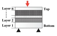
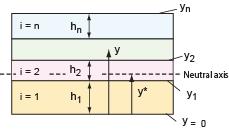
Figure 1. Multilayer material (n layers) - constructed with different materials and thicknesses
The desired function of the multilayer will determine both the materials used and their relative ordering in the multilayer stack. The outer layers are likely to be chosen to resist the operating environment, whereas the inner layers may be selected to provide barrier or electrical performance. In addition, the strength and stiffness of the multilayer as a whole can be tuned by optimizing the position of the layers. For example, a multilayer will be stiffer if the stiffest materials are used for the outer layers, as far from the neutral axis as possible. Whereas, locating them close to the neutral axis will result in a more flexible material.
In the case of unbalanced, or non-symmetrical, laminates, the orientation of the multilayer, relative to the primary load, is also important as the model calculations assume that layer 1 is on the bottom (loaded in tension), while layer n is on the top face (loaded in compression). As a result, non-symmetrical laminates can exhibit different flexural performance when flexed in different directions.
Furthermore, the model assumes that the failure stress is that which causes any one of the layers to yield (in tension or compression) and so does not account for other failure modes such as buckling or delamination.
So far we have spoken of the multilayer as a structure with layers
with different properties in a specific configuration. But we can also
think of it as a material with its own set of properties, and this
is useful because it allows comparison with more conventional materials.
To do this we calculate equivalent material properties for the
multilayer, identifying them by a tilde (e.g.  ,
,  ).
The quantities and
can be plotted on the modulus-density chart, allowing a direct comparison
with all the other materials on the chart. All the constructions using
material indices apply unchanged. We base the analysis on a multilayer
with the dimensions defined in Figure 1. The symbols
that appear in this section are defined here: symbols.
).
The quantities and
can be plotted on the modulus-density chart, allowing a direct comparison
with all the other materials on the chart. All the constructions using
material indices apply unchanged. We base the analysis on a multilayer
with the dimensions defined in Figure 1. The symbols
that appear in this section are defined here: symbols.
Density
The equivalent density of the multilayer (its mass divided by its volume) is:
Here fi is the volume fraction
occupied by layer i: 
Young's modulus
For multilayers we need to distinguish between the in-plane modulus
and that in bending. The effective in-plane modulus  is given, to an adequate approximation, by the rule of mixtures.
The in-plane modulus is simply the arithmetic mean of the components.

Flexural modulus
The flexural properties are quite different. The flexural stiffness is calculated by considering the multilayer in simple bending (with no contribution from shear).
Consider a multilayer with n layers, bent to a curvature K, positive when concave upwards. Plane sections remain plane (i.e. no shear). Define coordinate y such that y0 = 0.

The strain at y is ε
= ε0 - K y and the stress in the ith
layer is  where
where 


then N = C11 ε0 + C12 K and M = C12 ε0 + C22 K.
Identify the neutral axis:
N = C11 ε0 + C12 K
M* = M + N y*
M* = (C12 + C11 y*) ε0 + (C22 + C12 y*) K
Let ε0* = ε0 - K y* from which ε0 = ε0* + K y*
N = C11 ε0* + (C12 + C11 y*) K
M* = (C12 + C11y*) ε0* + (C22 + 2 C12 y* + C11 y*2) K
In simple bending N = 0, giving  therefore M* = B K


Yield strength (in-plane)
We calculate the in-plane yield strength using an equal strain assumption and find the stress required for one of the layers to exceed its maximum strain:


Flexural strength
The flexural strength of multilayer materials is taken as the stress required for one of the layers to yield. The maximum curvature is found by considering the maximum stress in each layer (either in tension or compression relative to the neutral axis). All layers below the neutral axis are taken to be in tension while all the layers above are assumed to be in compression. The maximum stress within each layer will occur at the face of the layer that is furthest from the neutral axis. The model only considers failure by layer yield and does not consider other failure mechanisms such as layer buckling or delamination.
The fully plastic failure moment is:

The equivalent flexural strength is then:


with σy,i equal to the yield or compressive strength depending on position of layer i relative to the neutral axis, and ydiff is the distance between the neutral axis and the edge of the layer that is experiencing the greatest stress.
Specific heat capacity
The volumetric specific heat,  ,
follows a rule of mixtures:
,
follows a rule of mixtures:
Thermal conductivity
The through-thickness conductivity,  ,
is given by the harmonic mean:
,
is given by the harmonic mean:

Thermal expansion
The through-thickness expansion coefficient is given by the weighted mean:

Electrical resistivity  (through thickness)

Dielectric constant
The dielectric constant of a multilayer, as with composites, is given by a rule of mixtures:
Dielectric loss tangent
The embodied energy is calculated as a simple rule of mixtures:
And as such only calculates the embodied energy of the constituent materials. It does not include the energy involved in processing or adhesives.
The same is true of the CO2 footprint. Only the relative proportions of the constituent materials are taken into account so it too is described by a rule of mixtures:
Copyright © 2019, Granta Design, Cambridge, UK