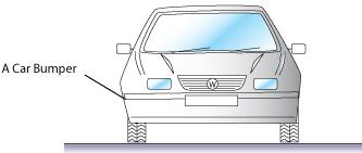
The materials used for car bumpers (Figure 1) have evolved with time. Originally, they were made from electroplated steel then aluminum was used. Starting from the 1980s, plastics were introduced: glass-reinforced polyesters and polyurethanes, modified polypropylene and blends of thermoplastic polyesters and polycarbonates. Plastic bumpers have the advantage of being lighter than their metal counterparts and they are better able to absorb energy in minor collisions without permanent damage.
Figure 1. A Car Bumper
A typical car bumper is made from glass-reinforced polyester. It weighs between 4 and 10 kg and has a minimum section thickness of 5 mm. The shape could be described as either a sheet (since the thickness is uniform) or a 3-D solid shape. The surface finish for the bumper should be 0.4 μm or better. The design requirements are listed in Table 1.
| Material Class | composite (thermoset-matrix) |
| Process Class | primary, discrete |
| Shape Class | 3-D-solid or sheet-dished-non-axisymmetric-shallow |
| Mass | 4 – 10 kg |
| Minimum Section (thickness) | 5 mm |
| Surface Finish (Roughness) | 0.4 μm |
| Batch Size | 100,000 |
Table 1. Car Bumper: design requirements
Figures 2–5 show the selection. Figure 2 shows the first of the selection stages: a bar chart of mass range against material class. Thermosets and polymer-matrix composites are selected from the material class menu. The selection box for the bumper is placed at a mass in the range 4–10 kg. Many processes pass this stage.
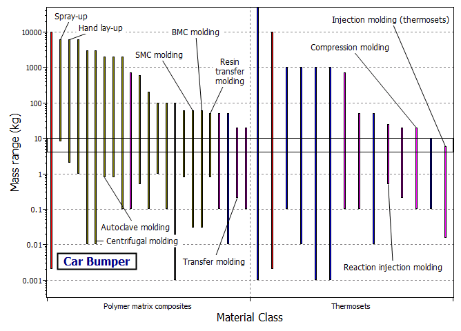
Figure 2. A chart of mass range against material class. The box isolates processes which can shape thermoset composites and can handle the desired mass range.
We next seek the subset of processes which can produce the shape (described as either a 'sheet-dished-nonaxisymmetric-shallow' or a '3-D-solid shape') and the desired section thickness. The corresponding chart is divided into two sections corresponding to each shape (Figure 3). In each section, the processes which can make that particular shape are plotted. The selection box specifies the requirement of a section thickness of about 5 mm which is within the capability of many processes.
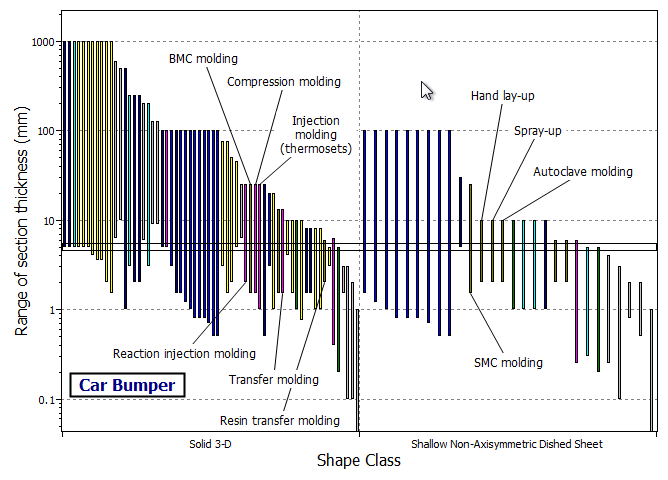
Figure 3. A chart of section thickness range against shape class. The chart identifies processes which can make 'sheet-dished-nonaxisymmetric-shallow' or '3-D-solid' shapes with sections of about 5 mm.
The next selection stage is shown in Figure 4. It is a bar chart of surface roughness against process class selecting primary from the process class menu. The selection box specifies a smoothness requirement of 0.4 μm or better. This is a demanding requirement of which many processes are not capable, as seen in the figure. Open-mold composite processes such as hand lay-up and spray-up fail for that reason.
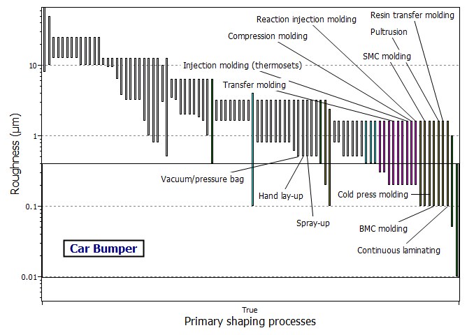
Figure 4. A chart of roughness against process class. The box isolates primary processes which are capable of roughness levels of 0.4 μm or better.
One further step is required in order to identify the processes which can produce the bumper cheaply. The appropriate chart (Figure 5) is that of economic batch size against process class. Only discrete processes are plotted on the chart. The selection box specifies a batch size of 100,000 for the bumper. Processes which have passed all the previous selection stages are labeled. The ones which can produce the bumper economically are listed in Table 2.

Figure 5. A chart of economic batch size against process class. The box identifies the processes which are economic for a batch size of 100,000.
| BMC molding |
| Compression molding |
| Injection molding – thermosets |
| SMC molding |
| Transfer molding |
Table 2. Processes for the car bumper
Several processes are technically capable of making the bumper (though the manufacturing cost varies greatly). The competitive ones for a large batch size of 100,000 bumpers are transfer molding, injection molding, compression molding, BMC and SMC molding.
Commercially, several processes are used depending on the volume of production: injection molding is used for high volume cars, whereas reaction injection molding and compression molding are used for medium volume production. The decisive factor is obviously the batch size.