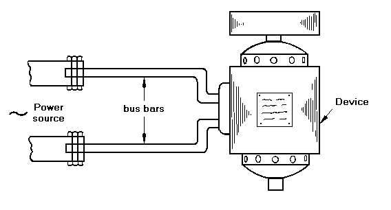
A bus bar is the element of an electrical circuit which delivers the current from the input source to the device which consumes it (Figure 31.1). The flex of a toaster is a bus bar, though one of low current-carrying capacity. Devices which consume large currents require massive bus bars to minimize the electrical losses external to the machine itself.
The current-carrying capacity of a bus bar is limited by temperature rise. Standards set values for this: it is typically 50°C above ambient, or roughly 90°C maximum. It is determined by the balance between the heat input (i2R) and the heat loss by convection, radiation and conduction. Convection and radiation generally dominate. Using typical values for the constants involved, a copper bus bar with a solid circular section can carry about 2 Amps per mm2 of cross section.

Figure 31.1 Bus bars transmit electrical power from the power source to the device which consumes it.
Bus bars are generally round or rectangular rods. The design criteria include high conductance, low cost, limited temperature rise, sufficient strength to carry self weight and service loads, and corrosion resistance (particularly resistance to oxidation which can create contact resistance at clamped connections). A sensible criterion for choosing a material for a bus bar is that the life cost should be minimized. That is, the capital cost, plus the cost of the energy dissipated as heat in the bus bar over its design life should be minimized. If this is used to select the initial subset of materials, other constraints (maximum temperature rise, sufficient strength and so forth) can then be applied. Table 31.1 summarizes the requirements.
FUNCTION |
Bus bar |
OBJECTIVE |
Minimize life cost (capital cost plus cost of resistive losses) |
CONSTRAINTS |
(a) Maximum temperature rise < 90°C |
(b) Adequate strength |
|
(c) Adequate oxidation resistance |
Table 31.1 The design requirements
Consider the design of a bus bar to minimize the total life cost, that is, the cost of the material of the bar plus that of the electric losses caused by its resistance. (The shape of the material is simple, so the cost of the bar is almost the same as that of the material.)
The first cost — the material cost — is simply
 , , |
(M31.1) |
where Cm is the cost per kilogram of the material, ρ is its density, A is the cross-section of the bar, and L is its length. The second cost — the resistance loss — is
 |
(M31.2) |
where Ce is the cost per kilowatt hour of the electricity, t (hours) is the operating life of the bar, and ρe the electrical resistivity of the material of which it is made. The life cost is approximately the sum of the two, and it is this that we wish to minimize. A large cross-section, A, gives low resistance but high material cost; a small A does the reverse. We must first locate the minimum value of
 . . |
Differentiating this with respect to A and setting the result equal to zero gives the optimum value for the cross-section:
 |
(M31.3) |
Substituting this back into the cost equation gives the objective function as
 . . |
(M31.4) |
The cost is minimized by selecting the material with the greatest value of
 . . |
(M31.5) |
Strength is important when a bus-bar of large span is unsupported or is exposed to other loads. Then we require a minimum value for the elastic limit, σel.
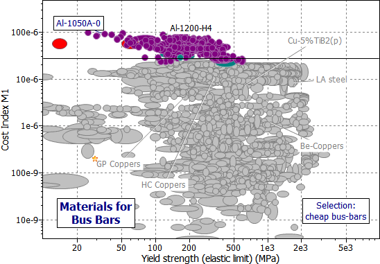
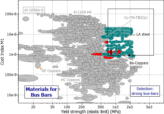
Figure 31.2 shows the appropriate chart — the index M1 plotted against elastic limit σel, using branches of the materials tree involving conductors.
When strength is not important, the high-conductivity aluminum alloys are the best choice for economical bus bars. But this ignores other aspects of choice — particularly those relating to oxidation. Oxidation leads to high contact resistance, and — particularly with aluminum — this causes problems. The next-best choice suggested by Figure 31.2 is that of general purpose (GP) or high-conductivity (HC) coppers, though they are significantly more expensive (lower value of M1). If strength is also important, the special conductor alloys based on Cu-Be-Co or, under extreme conditions, the composites Cu-Nb(f) or Cu-Al203(f) become the best choices. Table 31.2 summarizes the selection.

Figure 31.2(a) A chart of the index M1 plotted against elastic limit σel, using branches of the materials tree involving conductors. The selection shows the materials most appropriate for making low cost bus-bars.

Figure 31.2(b) A chart of the index M1 plotted against elastic limit σel, using branches of the materials tree involving conductors. The selection shows the materials best for making strong bus-bars.
MATERIAL |
COMMENT |
1000 series Aluminum alloys |
Cheapest, by a substantial margin |
HC Coppers, GP Coppers |
More resistant to oxidation than Al |
Beryllium-coppers |
High strength applications |
Copper-based composites |
Expensive, but strong, low resistance |
Table 31.2 Materials for bus bars
The optimization of equation (M31.3) gives the cheapest choice of bus bar as that for which the capital cost and the cost of the power dissipation are about equal. In general this means that the temperature of the bus bar rises when in use. So if the flex of your toaster gets warm when you make the toast, be reassured: your bus bar was designed with your pocket in mind.
'Copper Bus Bar Design Guide', Copper Development Association, Orchard House, Mutton Lane, Potters Bar, Herts EN6 3AP