.jpg)
Pressure vessels (Figure 15.1), from the simplest aerosol can to the biggest boiler, are designed for safety. Two ways of doing this are to arrange that they either yield or leak before they break. Small pressure vessels are usually designed to allow general yield at a pressure which is too low to propagate any crack the vessel may contain ('yield before break'). The distortion caused by yielding is easy to detect and the pressure can be released safely. With large pressure vessels this may not be possible. Instead, safe design is achieved by ensuring that the smallest crack that can propagate unstably has a length greater than the thickness of the vessel wall ('leak before break'). The leak releases pressure gradually and thus safely. The two criteria lead to slightly different performance indices, but essentially the same choice of materials. What are they?
.jpg)
Figure 15.1 A pressure vessel. It must be assumed that flaws pre-exist. The design and choice of material must ensure that they do not propagate.
|
FUNCTION |
Contain pressure, p |
|
OBJECTIVE |
Minimize cost |
|
Minimize weight |
|
|
CONSTRAINTS |
(a) Must yield before break, or |
Table 15.1 The design requirements
We idealize the pressure vessel as a thin-walled sphere of radius R and wall thickness t. (The material-selection aspects of the problem are independent of shape, so we choose the shape which offers the simplest analysis.) The mass of the vessel is:
 . . |
(M15.1) |
In pressure vessel design, the wall thickness, t, is chosen so that, at the working pressure p, the stress is less than the yield strength, σy, of the wall.
 . . |
(M15.2) |
A small pressure vessel can be examined ultrasonically, or by X-ray methods, or proof tested, to establish that it contains no crack or flaw of diameter greater than 2ac. The stress required to make such a crack propagate is
 , , |
(M15.3) |
where C is a constant near unity. Safety obviously requires that the working stress is also less than the fracture stress of equation (M15.3); but greater security is assured by requiring that the crack will not propagate even if, in an overload, the stress reaches the general yield stress. Then the vessel will deform stably in a way which can be detected. This condition is expressed by requiring that σf be greater than the yield stress, σy, giving
 . . |
(M15.4) |
The tolerable crack size is maximized by choosing a material with the largest value of
 . . |
(M15.5) |
Large pressure vessels cannot always be X-rayed or tested ultrasonically; and proof-testing them may be impractical. Further, cracks can grow slowly because of corrosion or cyclic loading, so that a single examination at the beginning of service life may not be sufficient. Then safety can be assured by arranging that a crack just large enough to penetrate both the inner and the outer surface of the vessel is still stable, because the leak caused by the crack can be detected. This is achieved by setting ac in equation (M15.3) equal to t/2:
 . . |
(M15.6) |
The wall thickness t of the pressure vessel was, of course, designed to contain the pressure p without yielding. From equation (M15.2), this means that
 . . |
(M15.7) |
Substituting this into the previous equation (with σf* = σy) gives
 . . |
(M15.8) |
The maximum pressure is carried most safely by materials with the large values of
 . . |
(M15.9) |
Both M1 and M2 could be made large by making the yield strength of the wall, σy, very small. Lead, for instance, has high values of both M1 and M2. But you would not choose lead for a pressure vessel because, to carry a useful pressure, the wall would have to be very thick. To minimize the wall thickness (equation M15.7) we must maximize either M1 or M2, and the index
 . . |
(M15.10) |
So far we have focused on stationary pressure vessels, for which weight is unimportant. Those which move (spacecraft, rocket casings, submersibles) must be both safe and light. The mass of the vessel is found by substituting equation (M15.7) into (M15.1)
 . . |
Therefore, the mass can be minimized by choosing materials with large values of the index
 . . |
(M15.11) |
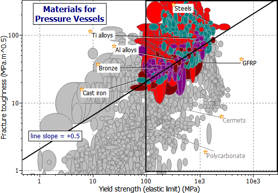
Safe minimum weight selection is achieved in two stages. For stationary vessels, both of these can be shown on the same chart (Figure 15.2). It shows the fracture toughness, K1c, plotted against elastic limit, σy. The two criteria M1 and M2 appear as lines of slope 1, and 1/2 respectively. Take 'leak before break' as an example. The diagonal line corresponding to M2 = K1c2 / σy = C excludes everything but the toughest steels, copper and aluminum alloys, though some polymers nearly make it (pressurized lemonade and beer containers are made of these polymers). The vertical line shows the 'wall thickness' index M3: efficient materials lie to the right of this line, and above the diagonal M2 index line. The selection is listed in Table 15.2(a).

Figure 15.2 A chart of fracture toughness K1c against elastic limit σy, showing the indices M2, and M3 = 100 MPa.

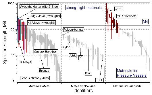
Figure 15.3 A chart showing M4. Strong, light materials lie near the top.
|
MATERIAL |
|
COMMENT |
|
Tough steels |
10 – 20 |
These are the pressure-vessel steels, standard in this application. |
|
Tough copper alloys |
10 – 20 |
OFHC hard drawn copper. |
|
Ti-Alloys |
8 – 15 |
Good performance but expensive |
|
High Strength Al-Alloys |
5 – 10 |
Less good than steel, copper or titanium |
Table 15.2(a) Materials for safe pressure vessels
|
MATERIAL |
|
COMMENT |
|
CFRP |
3 – 5 |
Considerable weight saving over metals, but expensive |
|
GFRP |
3 – 5 |
Considerable weight saving over metals |
|
Tough steels |
10 – 20 |
These are the pressure-vessel steels, standard in this application. |
|
Mg-alloys |
3 – 5 |
Low toughness makes Mg a poor choice |
|
Ti-alloys |
8 – 15 |
Good performance, but expensive |
|
High strength Al-alloys |
5 – 10 |
Less good than steel, copper or titanium |
Table 15.2(b) Materials for light pressure vessels
Light pressure vessels require that M4, rather than M3, be maximized. This can be achieved by adding a second stage in which M4 = σy / r is plotted as a bar-chart (Figure 15.3). The candidate materials are those with large values of both M2 and M4. They are listed in Table 15.2(b). In practice large pressure vessels are always made of steel. Those for models — for instance a model steam engine — are copper. Copper is favoured in the small scale application because of its greater resistance to corrosion. When weight is important, copper alloys are not a good choice; aluminum alloys, GFRP and CFRP offer the best combination of toughness, strength and low density.
Boiler failures used to be common place — there are even songs about it. Now they are rare, although when safety margins are pared to a minimum (rockets, experimental aircraft design) pressure vessels still occasionally fail. This (relative) success is one of the major contributions of fracture mechanics to engineering practice.
Background in fracture mechanics and safety criteria can be found in these books:
Brock, D (1984) 'Elementary Engineering Fracture Mechanics', Martinus Nijoff, Boston.
Hellan, K (1985) 'Introduction to Fracture Mechanics', McGraw-Hill.
Hertzberg, RW (1989) 'Deformation and Fracture Mechanics of Engineering Materials', Wiley, NY.