.jpg)
Heat exchangers take heat from one fluid and pass it to a second (Figure 25.1). The fire-tube array of a steam engine is a heat exchanger, taking heat from the hot combustion gases of the firebox and transmitting it to the water in the boiler. The network of finned tubes in an air conditioner is a heat exchanger, taking heat from the air of the room and dumping it into the working fluid of the conditioner. A key element in all heat exchangers is the tube wall or membrane which separates the two fluids. It is required to transmit heat, and there is frequently a pressure difference across it which can be large.
What are the best materials for making heat exchangers? Or, to be specific, what are the best materials for a conduction-limited exchanger with substantial pressure difference between the two fluids, one of them containing chloride ions (sea water). Table 25.1 summarizes these requirements.
.jpg)
Figure 25.1 A heat exchanger. There is a pressure difference Δp and a temperature difference ΔT across the tube wall which also must resist attack by chloride ions.
FUNCTION |
Heat exchanger |
OBJECTIVE |
Maximize heat flow per unit area, or per unit weight |
CONSTRAINTS |
(a) Support pressure difference Δp |
(b) Withstand chloride ions |
|
(c) Operating temperature up to 150°C |
|
(d) Low cost |
Table 25.1 The design requirements
First, a little background on heat flow. Heat transfer from one fluid, through a membrane to a second fluid, involves convective transfer from fluid 1 into the tube wall, conduction through the wall, and convection again to transfer it into fluid 2. The heat flux into the tube wall by convection (W/m2) is described by the heat transfer equation:
 , , |
(M25.1) |
in which h1 is the heat transfer coefficient and ΔT1 is the temperature drop across the surface from fluid 1 into the wall. Conduction is described by the conduction (or Fourier) equation, which, for one-dimensional heat-flow takes the form:
 , , |
(M25.2) |
where λ is the thermal conductivity of the wall (thickness t) and ΔT is the temperature difference (T2 − T1) across it. It is helpful to think of the thermal resistance at surface 1 as 1/h1; that of surface 2 is 1/h2; and that of the wall itself is t/λ. Then continuity of heat flux requires that the total resistance 1/U is
 , , |
(M25.3) |
where U is called the 'total heat transfer coefficient'. The heat flux from fluid 1 to fluid 2 is then given by
 , , |
(M25.4) |
where ΔT is the difference in temperature between the two working fluids.
When one of the fluids is a gas — as in an air conditioner — convective heat transfer at the tube surfaces contributes most of the resistance; then fins are used to increase the surface area across which heat can be transferred. But when both working fluids are liquid, convective heat transfer is rapid and conduction through the wall dominates the thermal resistance (1/h1 and 1/h2 are negligible compared with t/λ). In this case, simple tube or plate elements are used, making their wall as thin as possible to minimize t/λ. We will consider the second case: conduction-limited heat transfer. When the heat flow is adequately described by equation (M25.2).
Consider, then, a heat exchanger with n tubes of length L, each of radius r, and wall thickness t. The tubes must withstand a pressure difference Δp between the inside and outside, as in Figure 25.1. Our aim is to select a material to maximize the total heat flow, while safely carrying the pressure difference Δp. The total heat flow is
 , , |
(M25.5) |
where A is the total surface are of tubing, A = 2πrLn.
This is the objective function. The constraint is that the wall thickness must be sufficient to support the pressure difference Δp . This requires that the stress in the wall remains below the elastic limit, σy, of the material of which the tube is made (multiplied by a safety factor — which we can leave out):
 . . |
(M25.6) |
This constrains the minimum value of t. Eliminating t between equations M25.5 and M25.6 gives
 . . |
(M25.7) |
The heat flow per unit area of tube wall, Q/A, is maximized by maximizing
 . . |
(M25.8) |
Four further considerations enter the selection. It is essential to choose a material that can withstand corrosion in the working fluids, which we take to be water containing chloride ions (sea water). Cost will naturally be of concern. The maximum operating temperature must be adequate and the material should be available as drawn tube or as sheet which can be pressed to an appropriate shape.
A preliminary search (not shown) for materials with large values of M1, suggests copper alloys as one possibility. We therefore turn to the Copper Alloys branch of the materials tree for more help.

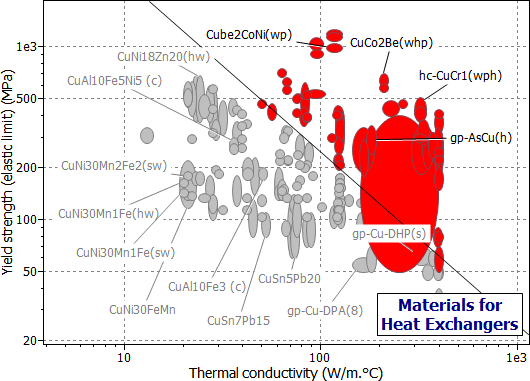
Figure 25.2 A chart of yield strength (elastic limit) σy against thermal conductivity, λ, showing the index M1, using the Copper Alloys branch of the materials tree.

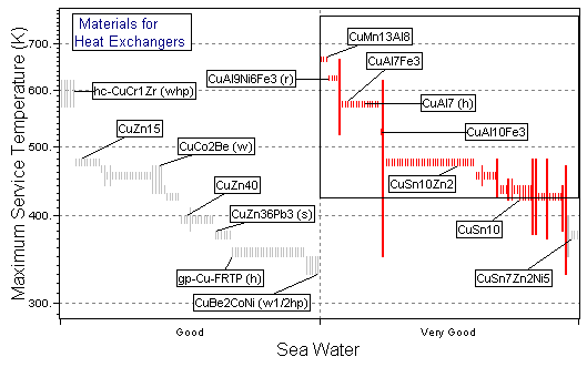
Figure 25.3 A chart of maximum service temperature, Tmax, against resistance to sea water ("Very Good" is best), using the Metals record subset with all branches contracted except for Non-ferrous Alloys\Copper.

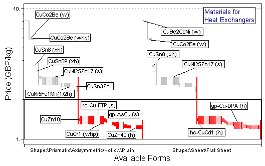
Figure 25.4 A chart of cost against available forms, selecting cheap materials available as tube or sheet (plate), using the Metals record subset with all branches contracted except for Non-ferrous Alloys\Copper.
The charts show the selection, made in three stages, using the Copper Alloys branch. The first stage (Figure 25.2) is a chart of σy versus λ, enabling M1 to be maximized. The second stage (Figure 25.3) shows maximum service temperature plotted as a bar-chart against resistance to sea water; the box selects material with Tmax > 150°C (423K), which are rated "Very Good" (on a scale "Very Poor" to "Very Good") in sea water. The last stage shows a bar-chart of material cost against available forms, selecting materials which are cheap and available as tube or sheet. The materials which pass all three stages are listed in Table 25.2: from among the 130 copper alloys, two groups have been identified.
MATERIAL |
COMMENT |
Aluminum-Bronzes, wrought |
An economical and practical choice |
Nickel-Iron-Aluminum-Bronzes, wrought |
More corrosion resistant, but more expensive |
Table 25.2 Materials for heat exchangers
Conduction may limit heat flow in theory, but unspeakable things go on inside heat exchangers. Sea water — often one of the working fluids — seethes with biofouling organisms which attach themselves to tube walls and thrive, like barnacles on a boat, creating a layer of high thermal resistance impeding fluid flow. Some materials are more resistant to biofouling than others; copper-nickel alloys are particularly good, probably because the organisms dislike copper salts, even in very low concentrations. Otherwise the problem must be tackled by adding chemical inhibitors to the fluids, or by scraping — the traditional winter pastime of boat owners.
It is sometimes important to minimize the weight of heat exchangers. Repeating the calculation to seek materials for the lightest heat exchanger gives, instead of M1, the index
 , , |
(M25.9) |
where ρ is the density of the material of which the tubes are made. (The strength σy is now varied to the power of 2 because the weight depends on wall thickness as well as density, and wall thickness varies as 1/σy (equation M25.6)). All copper alloys have roughly the same density, so there is little point in applying it within the copper alloys branch — but if copper alloys were to be compared with aluminum alloys or stainless steels, this would be relevant. Similarly, the cheapest heat exchangers are those made of the material with the greatest value of
 |
(M25.10) |
where Cm is the cost per kg of the material. Here aluminum alloys score because they are both light and cheap. The selections are not shown but can readily be explored using Granta EduPack.
JP Holman, 'Heat Transfer' 5th edition, (1981), McGraw-Hill, NY, USA.