The Controlled Thermal Expansion model predicts some of the properties exhibited by a novel type of lattice structure which uses two materials in a specific geometry to control the thermal expansion coefficient.
These lattices are still in the developmental stage and not commercially available. The Controlled Thermal Expansion model is a tool to investigate the theory and predict how this type of lattice may behave. Previous research work has been carried out on 2D lattices, however this model deals with 3D lattices.
The attraction of these lattices is that through optimization of the geometry (assuming suitable lattice materials have been chosen), the coefficient of thermal expansion can be controlled (it can be made zero or even negative). This is while remaining structurally robust, as they are stretch dominated lattices.
Click on Synthesizer on the
main toolbar and under  Controlled Thermal Expansion, click Dual
material lattice
Controlled Thermal Expansion, click Dual
material lattice
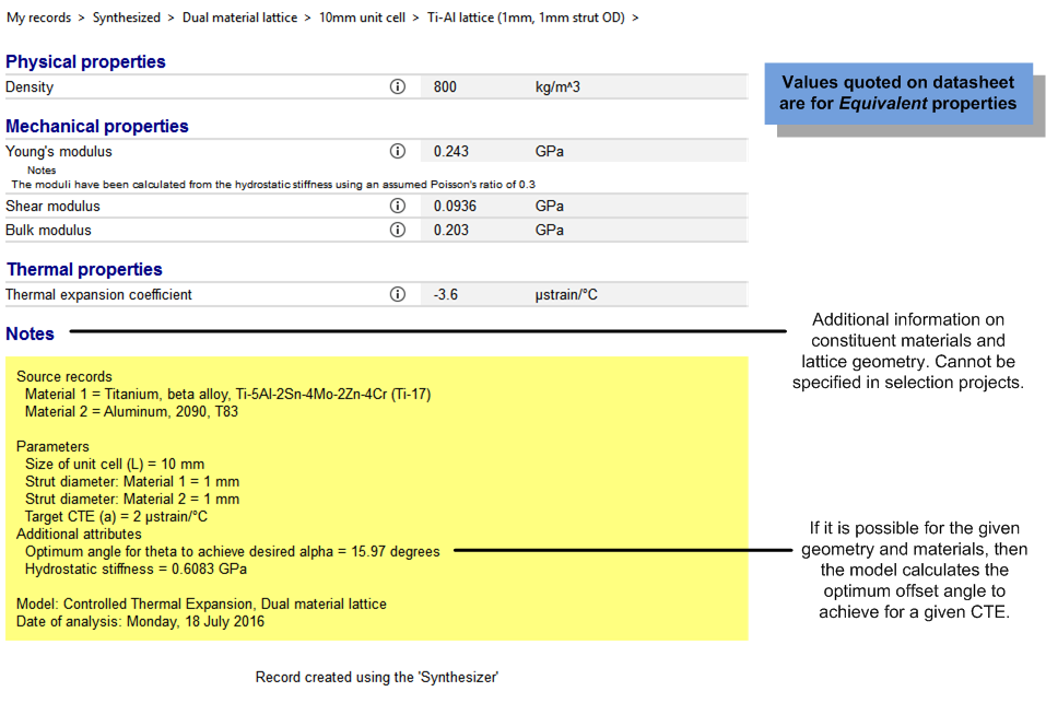
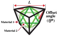
Material 1 is used for the outer lattice; Material 2 is used for the inner lattice.
To select a lattice Material, click . This displays the full MaterialUniverse tree for the active database. Browse the tree, highlight the material of interest and click .
If a low coefficient of thermal expansion (CTE) is required then it is advisable to use a material with a lower CTE for the outer lattice (Material 1), and a material with a higher CTE for the inner lattice (Material 2).
Specify the Offset angle (θ) of the outer lattice. This can be entered as either:
When a range is specified, the number of relative densities also needs to be specified in the Number of values box.
Specifying a list or range enables a family of lattices to be evaluated.
Specify the geometry of the lattice.
Enter the Size of the unit cell (L) of the outer lattice.
Enter a Strut diameter for Material 1 (the diameter of the beams of the outer lattice).
Enter a Strut diameter for Material 2 (the diameter of the beams of the inner lattice).
The units are shown to the right of the boxes.
The user can also specify a Target CTE (α) they wish the lattice to achieve. If this is possible with the materials chosen, then the model returns the optimum offset angle as a result in the notes field at the bottom of the datasheet.
In the Material boxes, type the abbreviated name. For example, if your source record is Aluminum, type Al. These are used to create the record names for the new lattice.
The synthesized records can be plotted on a chart for easy comparison with existing materials in the database.