.jpg)
Flywheels store energy. The energy can be recovered, either to smooth an intermittent power supply (as in reciprocating engines) or to drive something (a toy, a dynamo). Small flywheels like those in children's toys are made of lead. Steam, gasoline and diesel engines have cast iron flywheels. Innovative flywheels for power storage and regenerative braking systems for vehicles (Figure 6.1) are made of composites like GFRP. There is a great diversity of materials here. What is the best material for a flywheel?
An efficient flywheel stores as much energy per unit weight as possible, without failing. Failure (were it to occur) is caused by centrifugal loading. When the centrifugal stress: reaches the tensile strength (or fatigue strength) the flywheel flies apart. One constraint is that this should not occur.
The flywheel of a child's toy is not efficient in this sense. Its velocity is limited by the pulling-power of the child, and never remotely approaches the burst velocity. In this case, and for the flywheel of an automobile engine — we wish to maximize the energy stored per unit volume at a constant (specified) angular velocity. There is also a constraint on the outer radius, R, of the flywheel so that it will fit into a confined space.
The answer therefore depends on the application. The strategy for optimizing Flywheels for efficient energy-storing systems differs from that for children's toys. The two alternative sets of design requirements are listed in Table 6.1.
.jpg)
Figure 6.1 A flywheel. Its angular velocity (and thus the kinetic energy it can store) is limited by its strength.
FUNCTION |
Flywheel to store maximum kinetic energy |
Flywheel to run at constant (low) velocity |
OBJECTIVE |
Maximize kinetic energy per unit mass |
Maximize kinetic energy per unit volume |
CONSTRAINTS |
Must not burst. |
Outer radius, R, fixed. |
Adequate toughness (>20 MPa m1/2) |
Adequate toughness (>20 MPa m1/2) |
Table 6.1 The design requirements
The efficient flywheel stores as much energy per unit weight as possible, without failing. Think of it as a solid disk of radius R and thickness t, rotating with angular velocity ω (Figure 6.1). The energy U it stores is
 |
(M6.1) |
Here J = πρR4t / 2 is the polar moment of inertia of the disk and ρ the density of the material of which it is made. Therefore
 |
(M6.2) |
The mass of the disk is
 |
(M6.3) |
The quantity to be maximized is the kinetic energy per unit mass, which is the ratio of the last two equations:
 |
(M6.4) |
As the flywheel is spun up, the kinetic energy it stores increases, but so does the centrifugal stress. The maximum principal stress in a spinning disk of uniform thickness is
 |
(M6.5) |
where ν is Poisson's ratio. This stress must not exceed the failure stress of the disk. Since the disk is likely to be spun up and down repeatedly, we use the 'endurance limit' σe the stress below which the fatigue life is infinite. This sets an upper limit to the angular velocity, ω, and disk radius, R (the free variables). Eliminating Rω between the last two equations (with σmax = σe ) gives
 |
(M6.6) |
Poisson's ratio, ν, is roughly 1/3 for most solids, so we can treat it as a constant. The best materials for efficient flywheels are those with high values of the performance index
 |
(M6.7) |
It has units of kJ/kg.
To avoid failure due to fast fracture, the disc must also have adequate toughness. We achieve this by requiring that
 |
(M6.8) |
But what of the other sort of flywheel — that of the child's toy? Here we seek the material which stores the most energy per unit volume V at constant velocity. The energy per unit volume at a given ω is (from equation M6.2):
 |
(M6.9) |
Both R and ω are fixed by the design, so the best material is now that with the greatest value of
 |
(M6.10) |
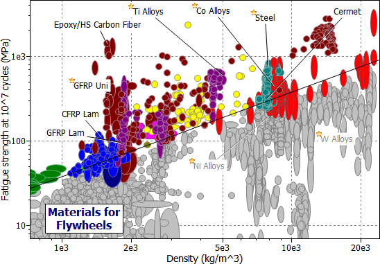
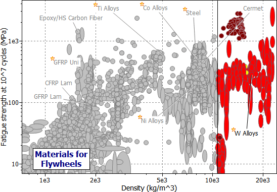
Figure 6.2 shows one way of using GRANTA EduPack to tackle both problems. It is a chart of endurance limit, σe , plotted against density, ρ. The heavy lines identify the search areas for each type of flywheel: they are completely different.
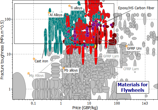
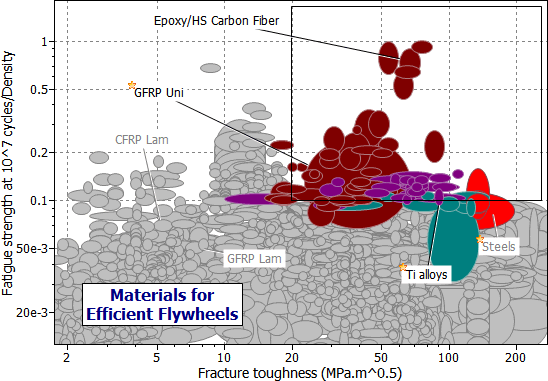
A second selection stage has been performed (Figure 6.3), limiting the selection to materials with K1c > 20 MPa m1/2 and Cm < 100 GBP/ kg. A more elegant way of exploring materials for efficient flywheels is shown in Figure 6.4, which combines both stages by using the compound property σe/ρ as the Y-axis. The results are listed in Table 6.2(a).

Figure 6.2(a) A chart of endurance limit, σe , against density, ρ, showing one possible selection with the M1 index.

Figure 6.2(b) A chart of endurance limit, σe , against density, ρ, showing the selection with the constraint M2 > 10 /m3.
The best choices for efficient flywheels are unexpected ones: polymer-matrix composites reinforced with continuous fibers of carbon or glass; or, less surprisingly, high-strength titanium alloys. Recent designs use a filament-wound glass-fiber reinforced rotor, and can store around 150 kJ/kg; a 20 kg rotor then stores 3 MJ or 800 kW hours.
The energy density in such a flywheel is considerable; its sudden release in a failure could be catastrophic. The disk must be surrounded by a burst-shield and precise quality control in manufacture is essential to avoid out-of-balance forces. This has been achieved in a number of glass-fiber energy-storage flywheels intended for use in trucks and buses, and as an energy reservoir for smoothing power flow in wind-power generation.

Figure 6.3 A chart of fracture toughness, K1c plotted against material price, Cm, as protection against brittleness and excessive cost.
The choice for the constant-velocity flywheel is quite different (Table 6.2(b)). Lead is good; it is the best choice for small flywheels. Cast iron is less good, but cheaper. It is the standard material for larger flywheels and for automotive applications. Gold, platinum and uranium are better than either of these, but may be thought unsuitable for other reasons.

Figure 6.4 A chart of specific endurance limit, σe /ρ, against fracture toughness, K1c, showing the selection for efficient flywheels.
MATERIAL |
M1 (kJ/kg) |
COMMENT |
Composites: CFRP |
200 – 350 |
The best performance — a good choice. |
Composites: GFRP |
150 – 200 |
Almost as good as CFRP and considerably cheaper — Excellent choice. |
Ti Alloys |
100 – 160 |
The best choice among metals — marginally better than high-strength steels because of lower ρ. |
High strength steels |
100 – 150 |
All about equal in performance. Steel and Al alloys are cheaper than Mg and Ti alloys. |
High strength Mg alloys |
80 – 100 |
|
High strength Al-alloys |
80 – 100 |
Table 6.2(a) Materials for efficient flywheels
MATERIAL |
M1 (kJ/kg) |
COMMENT |
Lead alloys |
3 |
High density makes these a good (and traditional) selection when performance is velocity-limited, not strength-limited |
Cast irons |
18 |
Table 6.2(b) Materials for constant velocity flywheels
And now a digression: the electric car. By the end of the century, electric cars will be using the roads, powered by a souped-up version of the lead-acid battery. But batteries have their problems: the energy density they can contain is low (see Table 6.3), and the weight of the battery limits both the range and the performance of the car. It is practical to build flywheels with an energy density of roughly 5 times that of a lead-acid battery. Serious consideration is now being given to the use of flywheels for electric cars. A pair of counter-rotating CFRP disks are housed in a steel burst-shield. Magnets embedded in the disks pass near coils in the housing, inducing a current and allowing power to be drawn by an electric motor which drives the wheels. It is estimated that such a flywheel could give an electric car a range of 600 km, at a cost competitive with a gasoline engine.
SOURCE |
ENERGY DENSITY |
COMMENT |
Gasoline |
20,000 |
Oxidation of hydrocarbon — mass of oxygen not included. |
Rocket fuel |
5,000 |
Less than hydrocarbons because oxidising agent forms part of fuel. |
Flywheels |
Up to 350 |
Attractive, but not yet proven |
Lead-Acid Battery |
40 – 50 |
Large weight for acceptable range |
Springs; rubber bands |
Up to 5 |
Much less efficient method of energy storage than flywheel. |
Table 6.3 Energy density of power sources
Lewis, G (1990) 'Selection of Engineering Materials', Prentice Hall, NJ, Part 1, p1.
Christensen, RM (1979) 'Mechanics of Composite Materials'. Wiley Interscience, NY, (1979), p 213 et seq.
Medlicott, PAC and Potter, KD (1986) 'The Development of a Composite Flywheel for Vehicle Applications', in 'High Tech — the Way into the Nineties', edited by Brunsch, K, Golden, HD, and Horkert, CM, Elsevier, Amsterdam, p 29.