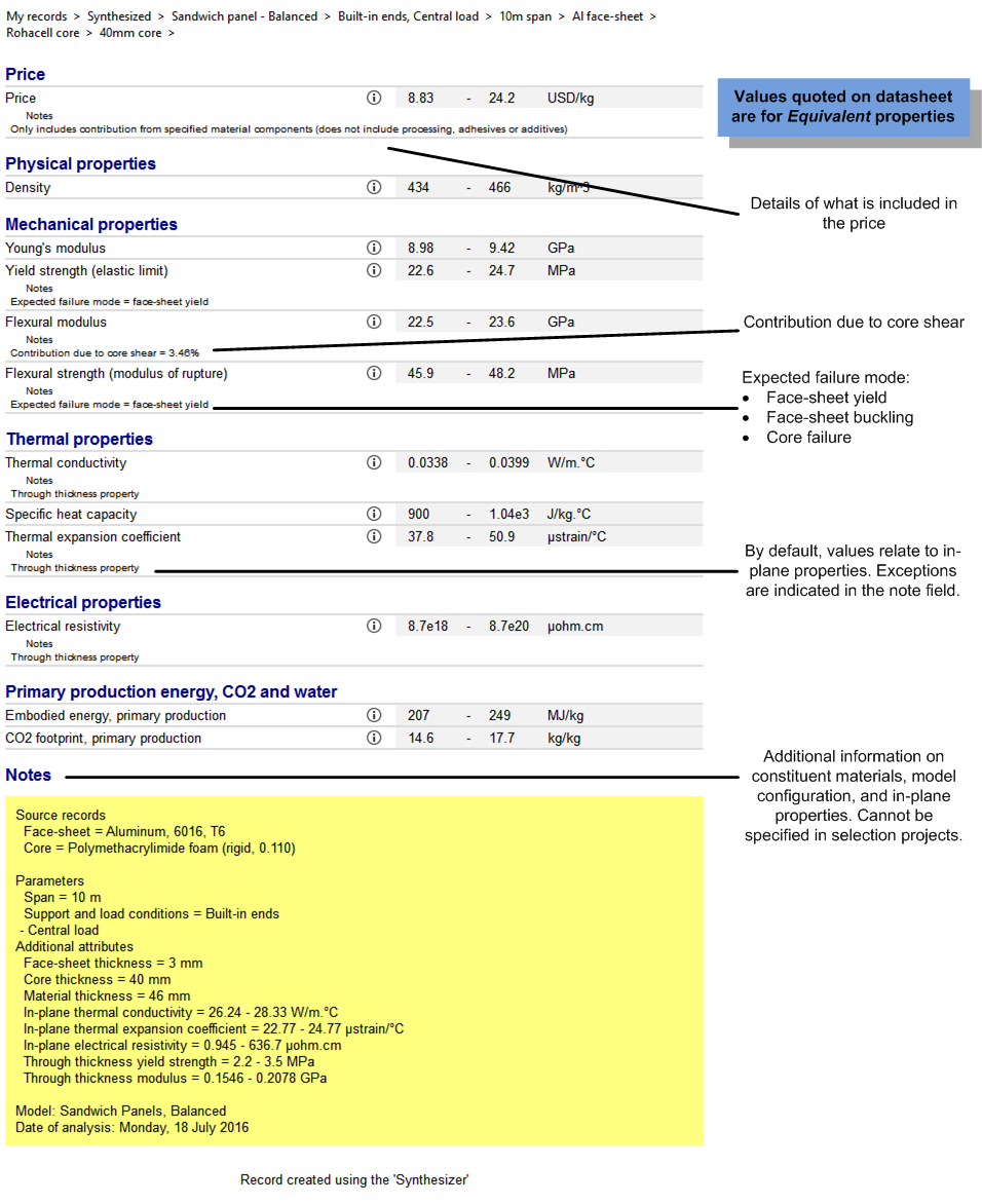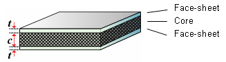
The Sandwich Panel model predicts the performance of lightweight sandwich structures, consisting of a core material bonded to two face-sheets. These structures are used in weight-critical applications, such as transportation vehicles.
When a monolithic material is loaded in bending, the top surface is subjected to tensile loads and the bottom surface to compressive loads. These loads, which are at a maximum at the outer surfaces, reduce to zero at the neutral axis. In contrast, the shear loads, which are zero at the outer surfaces, reach a maximum at the neutral axis.
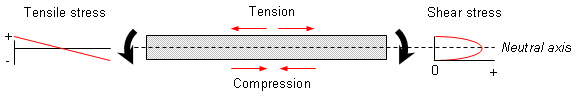
As the level of shear loading is typically an order of magnitude lower than the tensile/compressive loads at the outer surfaces, the performance of a monolithic material in bending is generally dictated by its tensile and compressive properties. This typically results in an inefficient use of material as only the outer surfaces of the component are exposed to the design load. Sandwich panel structures overcome this inefficiency by utilizing the stress distribution, and use lightweight, low performance materials in the core, and stiff, strong materials for the face-sheets. This enables the mass of the component to be minimized with little, or no, loss in performance.
Click on Synthesizer on the
main toolbar and under  Sandwich Panels, click Balanced.
To select the Face-sheet and Core materials, click . This displays the full MaterialUniverse tree for the active database. Browse the tree, highlight the material of interest and click .
The model variables define the thickness of the face-sheet and core materials. These can be entered as either:
When a range is specified, the number of thicknesses also needs to be specified in the Number of values box.
Specifying a list or range enables a family of sandwich panel configurations to be evaluated. For example, if five face-sheet and two core thicknesses are specified, then the performance of ten sandwich configurations will be predicted.
The model parameters specify the span, load and support configuration for the sandwich panel. These influence the stress distribution within the face-sheets and core material and determine the loading constants (B1, B2, B3 and B4).
Select the required 'load and support' condition from the drop-down menu.
| Support and load conditions | Loading constants | ||||
| B1 | B2 | B3 | B4 | ||
 |
Built-in ends, central load | 192 | 4 | 8 | 2 |
 |
Built-in ends, uniformly distributed load | 384 | 8 | 12 | 2 |
 |
Cantilever, central load | 3 | 1 | 1 | 1 |
 |
Cantilever, uniformly distributed load | 8 | 2 | 2 | 1 |
 |
Simply supported, central load | 48 | 4 | 4 | 2 |
 |
Simply supported, uniformly distributed load | 384/5 | 8 | 8 | 2 |
In the Face-sheet and Core boxes, type the abbreviated name. For example, if your source record is Aluminum, type Al. These are used to create the record names for the new sandwich panel materials.
The synthesized records can be plotted on a chart for easy comparison with existing materials in the database.