.jpg)
Shakers are devices for vibration-testing. They consist of an electromagnetic actuator driving a table, at frequencies up to 1000 Hz, to which the test-object (a space probe, an automobile or aircraft component or the like) is clamped (Figure 19.1). The shaker applies a spectrum of vibration frequencies, f, and amplitudes, A, to the test-object to explore its response.
A big table operating at high frequency dissipates a great deal of power. The primary objective is to minimize this, but subject to a number of constraints (Tustin and Mercado, 1984). The more important ones are summarized in Table 19.1. What materials make good shaker tables?
.jpg)
Figure 19.1 A shaker table. It must be light, stiff and have high damping.
|
FUNCTION |
Table for Vibration tester (Shaker table) |
|
OBJECTIVE |
Minimize power consumption |
|
CONSTRAINTS |
Radius, R, specified |
|
Must be stiff to avoid distortion by clamping forces |
|
|
Natural frequencies above maximum operating frequency (to avoid resonance) |
|
|
High damping to minimize stray vibrations |
|
|
Tough enough to withstand mishandling and shock |
|
|
Not too expensive |
Table 19.1 The design requirements
The power p (Watts) consumed by a dissipative vibrating system with a sinusoidal input is equal to
 , , |
(M19.1) |
where A is the amplitude (m), ω is the frequency (rad/s) and C1 is a constant. Provided the operating frequency ω is significantly less than the resonant frequency, then C1 ≈ 1. The amplitude A and the frequency ω are prescribed. To minimize the power lost in shaking the table itself, we must minimize its mass m. We idealize the table as a disk of given radius, R. Its thickness, t, is a free variable which we may choose. Its mass is
 |
(M19.2) |
where ρ is the density of the material of which it is made. The thickness influences the bending-stiffness of the table — and this is important both to prevent the table flexing too much under clamping loads, and because it determines its lowest natural vibration frequency. The bending stiffness, S, is
 , , |
(M19.3) |
where C2 is a constant. The second moment of the section, I, is proportional to t3R.
Thus, for a given stiffness S and radius R,
 , , |
where C3 is another constant. Inserting this into equation (M19.2) we obtain
 . . |
The mass of the table, for a given stiffness and minimum vibration frequency, is therefore minimized by selecting materials with high values of
 . . |
(M19.4) |
There are three further requirements. The first is that of high mechanical damping η. The second that the fracture toughness K1c of the table be sufficient to withstand mishandling and clamping forces. And the third is that the material should not cost too much.
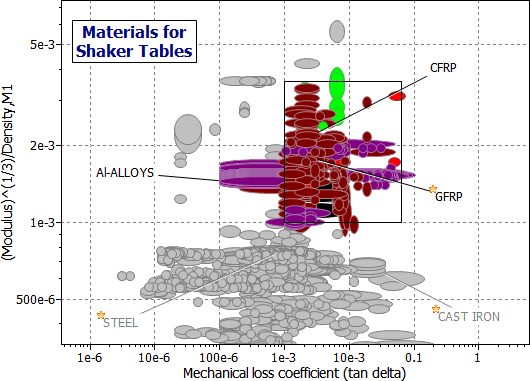
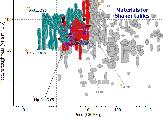
Figures M19.2 and M19.3 show one way of tackling the selection. The first shows the index M1 plotted against loss factor, η. The box isolates materials with high M1 and high h. The second allows a 'protective' stage to ensure adequate toughness (K1c > 15 MPa.m1/2) and to impose a limit on material cost (Cm < £10/kg). The intersection of the two stages gives the candidates listed in Table 19.2. Of these, magnesium and composites have high values of (E1/3/ρ), and both have low densities. Among metals, magnesium or the Metal Matrix Composite Al-SiC(p) are the best choices.

Figure 19.2 A chart of the index M1 = (E1/3/ρ) plotted against the loss coefficient, η, showing the selection.

Figure 19.3 A chart of fracture toughness K1c plotted against material cost, Cm.
|
MATERIAL |
Loss Coeff η |
M1 = (E1/3/ρ) |
COMMENT |
|
Mg-Alloys |
10-3 – 5 x 10⁻² |
2 |
The best combination of properties |
|
Al matrix MMCs |
10-4 – 2 x 10⁻³ |
1.5 |
Stiff; better damping than Al alloys |
|
Cast Irons |
2 x 10⁻³ – 10-2 |
0.7 |
Good damping but poor M1 |
|
GFRPs |
2 x 10⁻³ – 5 x 10⁻³ |
2 |
Less damping than Mg-alloys, but possible |
|
CFRPs |
10-3 – 3 x 10⁻³ |
3 |
Less damping than Mg-alloys or GFRP, but possible |
|
Short fiber GFRPs |
10-2 – 3 x 10⁻² |
1.5 |
Eliminated by poor K1c |
Table 19.2 Materials for shaker tables
Stiffness, high natural frequencies and damping are qualities often sought in engineering design. The shaker table found its solution (in real life as well as this case study) in the choice of a cast magnesium alloy.
Sometimes, a solution is possible by combining materials. The loss coefficient chart shows that polymers and elastomers have high damping. Sheet steel panels, prone to lightly-damped vibration, can be damped by coating one surface with a polymer, a technique exploited in automobiles, typewriters and machine tools. Aluminum structures can be stiffened (raising natural frequencies) by bonding carbon fiber to them: an approach sometimes used in aircraft design. And structures loaded in bending or torsion can be made lighter, for the same stiffness (again increasing natural frequencies), by shaping them efficiently: by attaching ribs to their underside, for instance. Shaker tables exploit shape in this way.
Tustin, W and Mercado, R (1984), 'Random Vibrations in Perspective' Tustin Institute of Technology Inc, Santa Barbara, CA, USA.
Cebon, D and Ashby, M F (1994), 'Materials Selection For Precision Instruments' Meas. Sci. and Technol. Vol 5 pp 296–306.