A barometer is a pressure actuator. Changes in atmospheric pressure, acting on one side of a diaphragm, cause it to deflect. The deflection is transmitted through mechanical linkage or electromagnetic sensor to a read-out. Similar diaphragms form the active component of altimeters, pressure gauges, and gas-flow controls for diving equipment. Their design requirements are summarized in the table: the diaphragm must be sensitive, remain elastic and, to be accurate, have low hysteresis or damping. What is the best material of which to make diaphragms?

Figure 12.1 A diaphragm for a pressure sensor. It must deflect under pressure, without creep or permanent deformation.
|
FUNCTION |
Diaphragm for pressure-sensing |
|
OBJECTIVE |
Maximize displacement for given pressure difference |
|
CONSTRAINTS |
Must remain elastic (no yield; no creep) |
|
Damping must be low for quick, precise response |
|
|
Cost a consideration in some instances |
Table 12.1 The design requirements
Figure 12.1 shows a diaphragm of radius a and thickness t. A pressure difference Δp = p1 − p2 acts across it. We wish to maximize the deflection of the center of the diaphragm, subject to the constraint that it remains elastic. The stresses throughout the material must be less than the yield or fracture stress, σf.
The deflection δ of a diaphragm caused by Δp depends on whether its edges are clamped or free. It is:
 |
(M12.1) |
with C1 = 3 / 16(clamped edges)
or C1 ≈ 9 / 8 (free edges).
Here E is Young's modulus, and ν is Poisson's ratio. The maximum stress in the diaphragm is
 |
(M12.2) |
with C2 = 1 / 2 (clamped edges)
or C2 ≈ 3 / 2 (free edges).
This stress must not exceed the yield or failure stress, σf, which we identify with the modulus of rupture, σMOR (the surface stress, in bending, at which yielding or fracture occurs).
The radius of the diaphragm is generally determined by the design; the thickness t is free. Eliminating t between the two equations gives
 |
(M12.3) |
The material properties are grouped in the last brackets. The quantity 1 − ν2 is close to 1 for all solids. Therefore, the best material for the diaphragm is that with the largest value of
 |
(M12.4) |
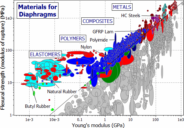
Figure 12.2 shows the chart we need: the modulus of rupture, σMOR, plotted against Young's modulus, E. The solid line shows the index M, positioned to leave a subset of materials exposed. They are listed in Table 12.2.

Figure 12.2 The modulus of rupture, σMOR, plotted against Young's modulus, E.
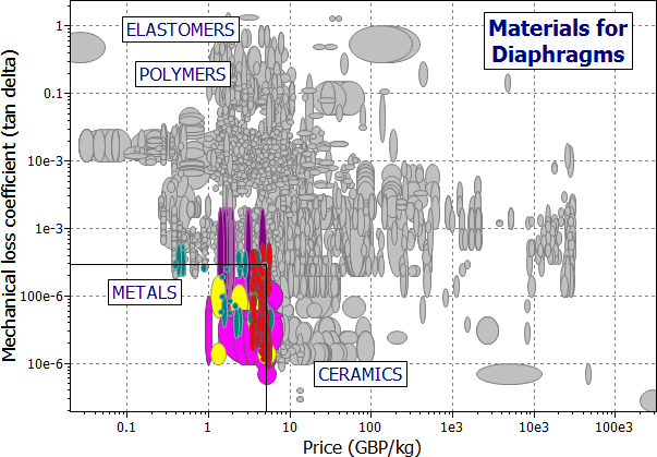
The remaining concerns are those of damping and cost. Figure 12.2 shows a chart of these two quantities, with a 'protective' selection box, the purpose of which is simply to eliminate materials which have high damping or are very expensive. Metals make good diaphragms, notably spring steel, and high-strength titanium alloys. Certain polymers are possible — nylon, polypropylene and PTFE — but they have higher damping, and may creep. So do elastomers: both natural and artificial rubbers. Table 12.2 lists the candidates.

Figure 12.3 The damping coefficient, η, plotted against cost/kg, Cm.
|
MATERIAL |
 |
COMMENT |
|
High-C steels |
0.3 – 0.37 |
The standard choice. Low loss coefficient gives rapid response |
|
Glasses |
up to 0.5 |
Possible if protected from damage |
|
Copper-beryllium alloys |
0.28 – 0.31 |
Good performance combined with corrosion resistance |
|
Bronzes |
0.1 – 0.15 |
|
|
Nickel-silvers |
0.12 – 0.14 |
|
|
High-strength wrought Al alloys |
0.12 – 0.15 |
Good performance and corrosion resistance |
|
Al-SiC MMCs |
0.1 – 0.14 |
|
|
Ti-Alloys |
0.2 – 0.3 |
As good as steel, corrosion resistant, but expensive |
|
Polymers |
0.1 – 0.3 |
Excellent M value, giving large elastic deflection. High loss coefficient limits response time; creep compromises precision |
|
Elastomers |
2 – 10 |
Table 12.2 Materials for diaphragms
As always, application of the primary design criterion (large δ without failure) leads to a subset of materials to which further criteria must be applied. Elastomers have the best values of M, but they have high damping, are easily punctured, and may be permeable to certain gases or liquids. If corrosive liquids (sea water, cleaning fluids) are likely to contact the diaphragm, then stainless steel or bronze may be preferable to a high-carbon steel, even though they have smaller values of M. This can be overcome by design: crimping the diaphragm or shaping it like a bellows magnifies deflection without increasing the stress, but adds to the manufacturing cost.
Ashby MF, "Materials Selection in Mechanical Design", 5th edition, Elsevier Butterworth-Heinemann, Oxford, UK, 2016.
Young, WC (1989) 'Roark's Formulas for Stress and Strain', 6th Edition, McGraw-Hill, NY, USA.